1. Measurement principle
The MagneW electromagnetic flowmeter uses Faraday's law of electromagnetic induction as its measurement principle. Faraday's law of electromagnetic induction states that "when a conductor moves in a magnetic field, an electromotive force is generated in the object."
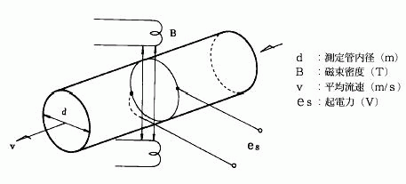
When applying this to the measurement principle of an electromagnetic flowmeter, we consider a conductive fluid instead of a conductive object and install electrodes to take out the generated electromotive force.

In the case of Fig. 1, the relationship between the average velocity v (m/s) and the electromotive force es (V) is as follows.

...and, the electromotive force es (V) proportional to the flow rate Q (m3/s) can be obtained.
The basic expression, Equation (1), is a theoretically derived expression that requires the following conditions:
- The magnetic field B, the two electrode axes, and the pipe axis are orthogonal to each other.
- The fluid is electrically homogeneous.
- The fluid is incompressible.
- All physical quantities are assumed to be uniform in the Z direction. The magnetic field exists over an infinite length in the tube axis direction.
- The inner wall of the pipe is an insulator, and the flow velocity is zero.
- The flow is centrosymmetric and is a function of the radius r only.
- The magnetic field is uniform and its magnitude is constant.
2. Flow rate and electromotive force
Observe the fluid flow and the electromotive force generated by it across the channel.


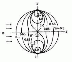
Fig. 2 shows the relationship between electromotive force and current when fluid moves only at point P of the channel cross section. If the fluid moves only at point P, as in this case, an electromotive force E is generated at this point in proportion to the magnetic flux density B and the flow velocity V according to Fleming's right-hand rule. This electromotive force E travels through the conductive fluid and is detected by electrodes a and b. This is only for point P. When the electromotive force generated at each point when the fluid is flowing in the flow path is detected by the electrode even if the magnitude is the same, the weight W is different and the relationship as shown in Fig. 3 is established. Under the conditions described in 1 Measurement principle, the average of the weighting factors at a certain distance γ from the tube center is constant, independent of γ, resulting in W = 1.0. As described above, if the flow is symmetric with respect to the tube axis, the flow velocity, that is, the flow rate can be measured as shown in Equation (1), regardless of the viscosity, density, temperature, flow velocity distribution, or electrical conductivity of the fluid.
3. Excitation method
In the 70s, there were two excitation methods for electromagnetic flowmeters, DC excitation and AC excitation, but at that time, the AC excitation was used for most industrial electromagnetic flowmeters. The AC excitation method has some drawbacks such as lack of stability at the zero point, as well as susceptibility to quadrature noise and power supply noise. MagneW ™ electromagnetic flowmeters are the first in the world to use a square-wave excitation method to eliminate these drawbacks.
In the suquare-wave excitation method, as shown in Fig. 1-1-4, the constant current from the constant current circuit is switched by the command pulse from the pulse generation circuit, and the positive and negative constant currents flow through the excitation coil.
The command pulse from this pulse generator is synchronized to the power frequency, so it is less affected by power supply noise.

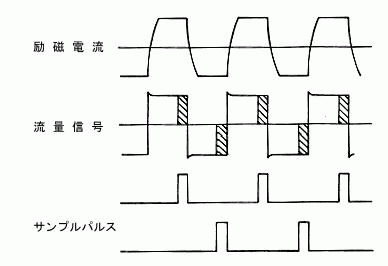
Likewise, as shown in Fig. 5, the excitation current becomes constant after a delay due to the time constant of the excitation coil.
The magnetic field is proportional to the excitation current, so it has the same square shape as the excitation current.
The electromotive force is proportional to the magnetic field strength and the average flow velocity, but the change in the degree of magnetic flux that is confined in a closed circuit consisting of electrodes, fluid and lead wires induces electromagnetic induction noise, resulting in a signal as shown in Fig. 5.

Sampling is performed when the flow signal reaches a steady value, so that the flow signal is not affected by electromagnetic induction noise.
Basic conditions for correct accuracy
- The fluid must be electrically uniformly and conductive: It is difficult to measure the electromotive force of non-conductive fluid.
- The pipe must be full of water: The volume that is not filled leads to an error.
- The fluid must be homogeneous: If the conductivity distribution is uneven, the grounding will be uneven, leading to an error.
- The fluid must be non-magnetic: If the fluid is magnetic, the magnetic flux density distribution changes, and correction is required.