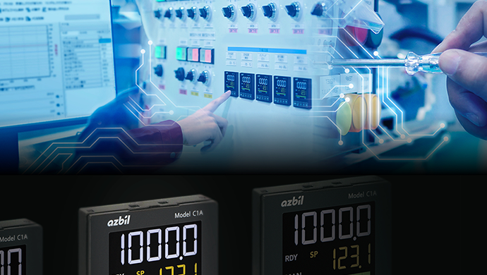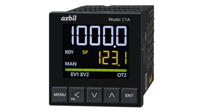
For everything from installation to maintenance, workload is reduced.
High performance and usability overturn preconceptions about what a 48 × 48 mm controller can do.
- Accuracy: ± 0.1 %. Sampling cycle: 25/50/100/300/500 ms (specifiable)
- Design & installation: easy connection with PLC link function
- Operation & management: PID simulator available
- Maintenance: pullout structure for easy replacement
Design and installation
Screwless terminals
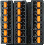
In addition to models with common screw terminal blocks, models with push-in terminals are now available. The adoption of spring terminal blocks prevents loosening caused by vibration and eliminates the need for retightening, reducing maintenance man-hours. Wiring can be completed simply by inserting ferrule connectors without tools, drastically reducing the man-hours for wiring. Each terminal has two holes/polarities to facilitate crossover wiring for power supply and RS-485 communication.
PLC link communication
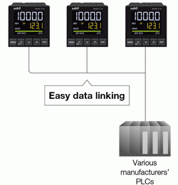
Generally speaking, to enable a digital indicating controller to communicate with a host system, a program for communication must be designed on the host system. Model C1A provides a PLC link communication function that enables data communication without the need to create a communication program.
Communication can easily be enabled by selecting a supported protocol and communication items in Smart Loader Package, which reduces program design and debugging workloads for architects.
| Supported protocol | Connectable model examples |
|---|---|
| Mitsubishi/QnA-compatible 3C frame model 4 | MELSEC iQ-R, MELSEC Q from Mitsubishi Electric |
| Mitsubishi A-compatible 1C frame model 4 | MELSEC F from Mitsubishi Electric |
| Omron FINS (host link) | CS, CJ, CP, NJ, NX from Omron |
| KEYENCE protocol mode 4 | KV-8000/7000/5000/3000 from KEYENCE |
| Modbus™/RTU | RTU devices |
Operation and management
Large LCD screen
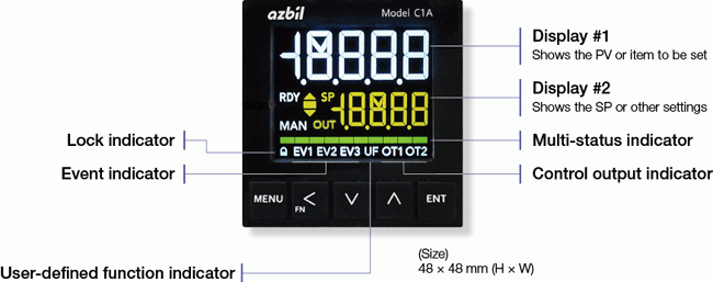
The large LCD screen provides superior visibility and can display a 4.5-digit number (−19999 to 19999).
In addition, the built-in multi-status indicator serves various purposes, such as blinking when an alarm occurs and displaying a bar graph of operational output to a control element in percentage terms and in an SP/PV deviation graph.
Multiple controllers are used at many actual manufacturing sites. Accurately identifying the ones generating alarms and those in abnormal control states can contribute to safety and the stable operation of equipment.
Smart Loader Package
The Smart Loader Package enables you to change various C1A settings, such as parameters, monitoring, and calibration, on your PC. The Smart Loader Package can be downloaded for free from our website.
Model C1A can be powered by a USB cable, and its parameters can be read and written when it is powered from a PC.
PID simulator
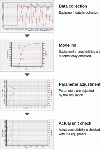
The PID simulator is a built-in function of the Smart Loader Package that helps you to adjust PID values.
It creates a mathematical model that recreates process characteristics from operating data, thereby enabling simulations of PID control on a PC. This enables you to adjust the PID values without repeatedly operating the actual equipment, significantly reducing the man-hours required for adjustment. The screen shows process variations for intuitive adjustment.
The simulator aids overshooting and hunting reduction work. It helps you reduce the time required for trial run adjustment and improve the takt time and quality of equipment.
Servicing and maintenance
Easy replacement
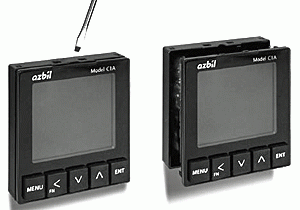
At manufacturing sites, many different kinds of problems can occur suddenly. Among them are unexpected device failures. Promptly restoring such devices to their original states is critical. Model C1A can be replaced by simply pulling it out from the front of the case, without removing the wiring from the rear terminals. This reduces the maintenance workload and prevents problems resulting from incorrect rewiring.
Inquiries about control products
