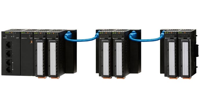
Equipped with Ethernet Modbus™ or TCP communication as a standard feature, these modules enable multi-loop cooperative control and other types of advanced control technology and networking.
- Support for high-capacity communication: Ethernet communication
- Optimization functions (process simulation, control of temperature difference between zones)
- More environmentally friendly control (peak power suppression control, optimal start-up control)
- Controller module
Accuracy: ± 0.1 % FS (model NX-D35), sampling cycle: 100 ms, number of control channels: 4
Product Video
Lineup
| Name and model | Controller Module | |||
|---|---|---|---|---|
| NX-D15 | NX-D25 | NX-D35 | ||
| Appearance | Image

| Image
| Image
| |
| Control loops | 4 | 2 or 4 | ||
| Sampling cycle | 500ms | 200ms | 100ms | |
| Accuracy | ±0.3% FS ±1 digit | ±0.1% FS ±1 digit | ||
| Input | Thermocouple, resistance temperature detector, DC voltage, DC current | |||
| Output | Transistor | ✓ | ||
| Analog current | ✓ | |||
| Analog voltage | ✓ | |||
| Transistor (motor) | - | ✓ | ||
| Rated power supply voltage | 24 VDC | |||
| External dimensions (mm) | H100×W30×D104 | |||
| Specifications Sheet | Network Instrumentation Modules Controller Module Model NX-D15/D25/D35 | |||
| Model No. | Smart Device Gateway |
|---|---|
| NX-SVG | |
| Appearance | Image

|
| Interface | Ethernet: 2 channels RS-485: 2 channels (selectable from CPL and Modbus™/RTU) USB host communication: USB 2.0 |
| Rated power voltage | 24 V DC |
| External dimensions (mm) | H100 × W45 × D85 |
| Specifications Sheet | Network Instrumentation Modules Smart Device Gateway Model NX-SVG |
*A communication gateway that enables data exchange among a wide variety of control devices without the need for programs, making development work smarter.
| Name and model | Supervisor Module | ||
|---|---|---|---|
| NX-S11 | NX-S12 | NX-S21 | |
| Appearance | Image

| ||
| Control loops | 32 | ||
| Features | Control of temperature difference between zones | Optimal start-up control | Peak power suppression control |
| Rated power supply voltage | 24 VDC | ||
| External dimensions (mm) | H100×W30×D85 | ||
| Specifications Sheet | Network Instrumentation Modules Supervisor Modules Model NX-S11/S12/S21 | ||
| Name and model | Digital Input ModuleNX-DX1 | Pulse Input ModuleNX-DX2 | Digital Output ModuleNX-DY1 | Digital Output ModuleNX-DY2 |
|---|---|---|---|---|
| Appearance | Image

| Image
| Image

| Image
|
| Inputs | 16 | - | ||
| Outputs | - | 16(sink) | 16(source) | |
| Rated power supply voltage | 24 VDC | |||
| External dimensions (mm) | H100×W30×D104 | |||
| Specifications Sheet | Network Instrumentation Modules Digital Input Modules Model NX-DX1/DX2 | Network Instrumentation Modules Digital Output Modules Model NX-DY1/DY2 | ||
| Name and model | Communication BoxNX-CB2 | Communication AdapterNX-CL1/CR1 | Terminal AdapterNX-TL1/TR1 |
|---|---|---|---|
| Appearance | Image

| Image

| Image
|
| Ports | 4 | 1 | |
| Mounting method | DIN rail | ||
| Rated power supply voltage | 24 VDC | - | |
| External dimensions (mm) | H100×W30×D85 | H100×W20×D26.4 | H100×W20×D36.5 |
| Specifications Sheet | Network Instrumentation Modules Communications Box (Model NX-CB1), Communications Adapter (Model NX-CL1/CR1), Terminal Adapter (Model NX-TL1/TR1) | ||
| User's Manual | Network Instrumentation Module Model NX-CB2 Communication Box User's Manual for Installation | - | |
Inquiries about control products