The model AUR455 dynamic self-checking burner controller can be used for both continuous operation and batch operation. It is a combustion safety controller that employs the correct ignition sequence to automatically and safely ignite gas burners and oil burners. This device can be used in combination with the model AUD300C advanced ultraviolet flame detector, the model AUD500C explosion-proof advanced ultraviolet flame detector, or a flame rod.
- The design complies with JIS C 9730-2-5 and JIS C 9730-1.
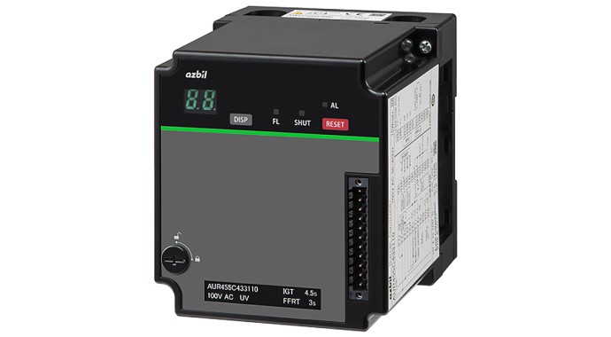
- The combustion sequence, alarm codes and flame voltage are shown on the 7-segment display.
- Self-diagnosis of the internal control relay circuit
- Equipped with host communications (RS-485) to enable remote monitoring of status
Model AUR455 dynamic self-checking burner controller can be used for both continuous operation and batch operation. It is a combustion safety controller that follows the correct ignition sequence to automatically and safely ignite gas burners and oil burners. This device can be used in combination with model AUD300C advanced ultraviolet flame detector, model AUD500C explosion-proof advanced ultraviolet flame detector, or a flame rod. Model AUR455 drives the shutter that is built into model AUD300C / AUD500C to continuously check both its own flame detection circuit and the ultraviolet detector in order to provide flame detection for continuous burner operation.
Also, when used with a flame rod,model AUR455 continuously checks its own built-in flame detection circuit to provide flame detection for continuous burner operation.
The front connector provides a communication function and event output that are convenient for maintenance and troubleshooting. Note particularly that the PC loader can read out various kinds of data recorded in model AUR455 using the RS-485 communications protocol.
Additionally,the front 7-segment display shows the flame voltage and the current operating status. When an alarm is activated, the display indicates an operating status and an alarm code so that the details can be checked easily.
- The combustion sequence, alarm codes and flame voltage are shown on the 7-segment display.
- LED indicators show whether there is a flame signal and indicate lockout.
- Self-diagnosis of the internal control relay circuit
- If lockout occurs due to ignition failure or unexpected flame failure, the controller does not restart without a manual reset
- The design complies with JIS C 9730-2-5 and JIS C 9730-1.
- Equipped with host communications (RS-485) to enable remote monitoring of status
Inquiries about control products